|
| |
|
| Documents:
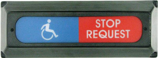
FAC-01423-00000, Display RCT-00786 & RCT-01414.pdf SYSTEM DISPLAY & ADA DISPLAY
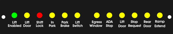
System Indicator; "Egress Window", "Stop Request", "Lift Door", "ADA Stop Request", "Rear Door" and "Entry Door". Connects to dash PCB's, PCB-00789-J4, PCB-00948-J4, PCB-01067-J5 or PCB-01083-J5.
ADA System Indicator; "Lift Enabled", "Lift Door", "Shift Lock", "In Park", "Park Brake" and "Lift Switch". Interfaces and connects to; "Bus Power Systems, RCT-00786-J3 Barrier-Strip or RCT-01414-J3 Plug-In-Play units.
Data cable Must Be Ordered Separately.
DAT-01348-00XX0. (XX depicts total cable length.) |
|
| |
|
| Documents:
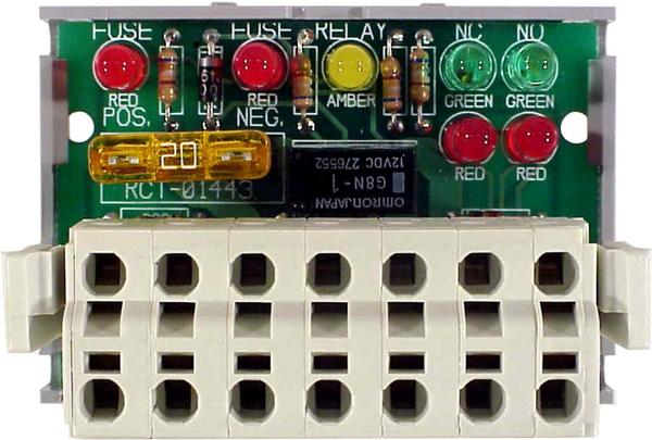
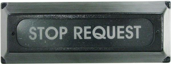
RCT-01444-00000 System Display Bus Power Center.pdfSystem Indicator; "Egress Window", "Stop Request", "Lift Door", "ADA Stop Request", "Rear Door" and "Entry Door".
Interfaces to; "Bus Power Systems", RCT-00786 Barrier-Strip or RCT-01414 Plug-In-Play units.
Connects to PCB's, PCB-00789-J4, PCB-00948-J4, PCB-01067-J5 or PCB-01083-J5.
Data cable Must Be Ordered Separately.
DAT-01348-00XX0. (XX depicts total cable length.) |
|
| Documents:
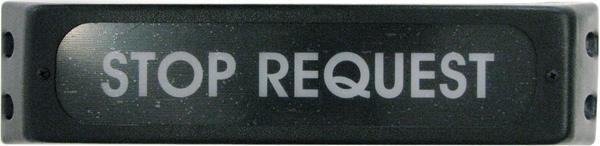
RCT-01444-00001 System Display Bus Power Center.pdfSystem Indicator; "Egress Window", "Stop Request", "Lift Door", "ADA Stop Request", "Rear Door" and "Entry Door".
Interfaces to; "Bus Power Systems", RCT-00786 Barrier-Strip or RCT-01414 Plug-In-Play units.
Connects to PCB's, PCB-00789-J4, PCB-00948-J4, PCB-01067-J5 or PCB-01083-J5.
Data cable Must Be Ordered Separately.
DAT-01348-00XX0. (XX depicts total cable length.) |
|
| Documents:
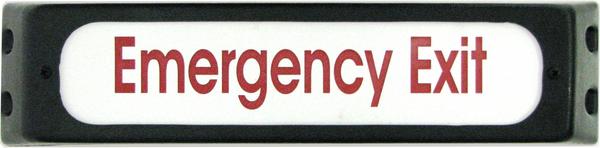
RCT-01444-00002 System Display Bus Power Center.pdfSystem Indicator; "Egress Window", "Stop Request", "Lift Door", "ADA Stop Request", "Rear Door" and "Entry Door". Interfaces to; "Bus Power Systems", RCT-01760-00000. Connects to PCB's, PCB-00789-J4, PCB-00948-J4, PCB-01067-J5 or PCB-01083-J5. Data cable Must Be Ordered Separately. DAT-01348-00XX0. (XX depicts total cable length.) |
|
| Documents:
RCT-01459-00000 System & ADA Displays.pdfSYSTEM DISPLAY & ADA DISPLAY
System Indicator; "Egress Window", "Stop Request", "Lift Door", "ADA Stop Request", "Rear Door" and "Entry Door". Connects to dash PCB's, PCB-00789-J4, PCB-00948-J4, PCB-01067-J5 or PCB-01083-J5.
ADA System Indicator; "Lift Enabled", "Lift Door", "Shift Lock", "In Park", "Park Brake" and "Lift Switch". Interfaces and connects to; "Bus Power Systems, RCT-00786-J3 Barrier-Strip or RCT-01414-J3 Plug-In-Play units.
Data cable Must Be Ordered Separately.
DAT-01348-00XX0. (XX depicts total cable length.) |
|
| Documents:
RCT-01459-00001 System & ADA Displays. SYSTEM DISPLAY & ADA DISPLAY
System Indicator; "Egress Window", "Stop Request", "Lift Door", "ADA Stop Request", "Rear Door" and "Entry Door". Connects to dash PCB's, PCB-00789-J4, PCB-00948-J4, PCB-01067-J5 or PCB-01083-J5.
ADA System Indicator; "Lift Enabled", "Lift Door", "Shift Lock", "In Park", "Park Brake" and "Lift Switch". Interfaces and connects to; "Bus Power Systems, RCT-00786-J3 Barrier-Strip or RCT-01414-J3 Plug-In-Play units.
Data cable Must Be Ordered Separately.
DAT-01348-00XX0. (XX depicts total cable length.) |
|
| Documents:
RCT-01460-00000 ADA System Display.ADA System Indicator; Lift Enabled, Lift Door, Shift Lock, In Park, park Brake and Lift Switch.
Interfaces and connects to; "Bus Power Systems", RCT-00786-J3 Barrier-Strip or RCT-01414-J3 Plug-In-Play units.
Data cable Must Be Ordered Separately.
DAT-01348-00XX0. (XX depicts total cable length.) |
|
| |
|
| Documents:
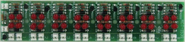
PCB-01539-00000 Zone Monitor.PCB mounted behind engraved faceplate.
Both positive and negative inputs may be input for each zone.
A positve or negative output is available when any input 1 thru 8 zone is active. |
|
| |
|
| |
|
| |
|
| |
|
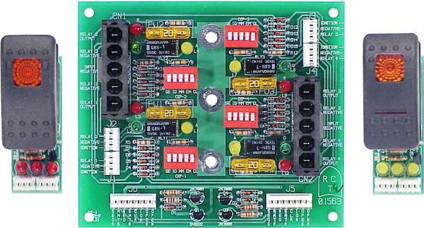
| Documents:
RCT-01563-00000 Ambulance, Aux. Power Card.Adds four circuits to the Ambulance Power Center, RCT-01479.
When ordering this control the switching (RCT-01564) must be ordered as well. Switches that can be used. "ON-OFF-ON" or "ON-OFF". Either maintained or momentary. When using "ON-OFF-ON" switch , two of the four power relays on the Aux. Power Card, RCT-01563 will be used. |
|
| |
|
| |
|
| |
|
| |

 Home
Home